
CISC and RISC
There are two main types of computer architectures that will be covered in this project: Complex Instruction Set Computing (CISC) and Reduced Instruction Set Computing (RISC).
An example of CISC is the x86 architecture. Examples of RISC are the ARM, the MIPS, and the PowerPC architectures.
The differences between CISC and RISC is their behaviors in how they execute instructions.
CISC
The CISC architecture aims to complete a task in as few assembly instructions as possible. This is done with an emphasis on building rich instruction sets with an emphasis on complex hardware.
The hardware in a CISC system must have the ability to interpret several series of operations at a given time.
The CISC architecture uses microcode,which is the interpreter between the hardware of a computer and the architectural level of a computer.
Characteristics of the CISC instruction set include:
- 2-operand format: instructions have a source and destination
- Multiple addressing modes for memory
- Instructions that take multiple clock cycles to execute
An example of a CISC instruction would be one that performs multiple jobs at once. There could be an instruction called MULT that will load two values into registers, multiply them, and then store the result in another register.
There are drawbacks to CISC as well.
These include the increased complexity of an instruction set, as each new chip hardware generation must maintain the same properties of the previous generation.
Since CISC attempts to execute code in as few instructions as possible, the compensation is that the instructions will take more clock cycles to execute.
The complexity of CISC can be shown in the flow diagram below.
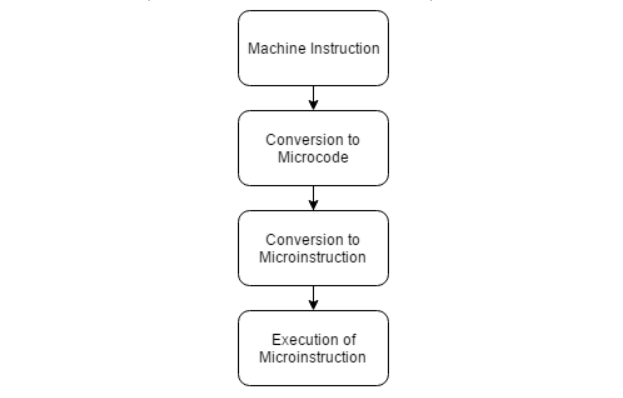
CISC starts with the machine instructions, converts them to microcode, then converts to microinstructions, which is then executed.
RISC
The RISC instruction set focuses on using more simple instructions that can each be executed in just one clock cycle.
From the CISC example shown above, the RISC equivalent would split up the MULT instruction into three different instructions: LOAD, MULT, and STORE.
The RISC instruction set is more emphasized on software. Separating commands into multiple instructions allows for pipelining and more efficient use of hardware.
Characteristics of the RISC instruction set include:
- More optimized register usage with 32 or more registers
- Simplified compiler design by using general purpose registers
- Use registers instead of the stack to pass arguments and hold variables
- Reduced number of instructions (compared with
CISC)
The main drawback to RISC is increased instruction size from having more instructions.
Since RISC processors depend on compilers to explicitly emit each instruction, the compilers will determine the performance of the program.
The flow diagram of RISC is shown below, which is much less complex than CISC.

The machine instruction is executed immediately. There are no conversions that need to be made.
x86
This section will give a brief overview on how to interpret x86 assembly code.
The x86 architecture has eight general purpose registers, each 32-bits in size which can be seen below
1 | EAX –Extended Accumulator Register |
The x86 architecture uses the stack as the part of memory to store local variables and function arguments.
The stack has a Last In First Out (LIFO) structure. The ESP and EBP registers are associated with the stack, where the ESP (stack pointer) always points to the top of the stack.
The EBP (base pointer) is the reference on the stack that never changes. The ESP register is the pointer to the top of the stack when the function is first called.
Arithmetic operations follow the same general syntax.
For addition and subtraction, the syntax is ADD/SUB dest, src. Where ADD/SUB is the operation and dest is the destination register and src is the source register.
Example instructions are shown below.
1 | add eax, 7 |
There are three possible ways to perform multiplication.
There is multiplication of
- just the
eaxregister with a value, - two values stored into a register
- a register with a value stored into that same register.
The first way only has 1 argument. This means that the eax register is taken and multiplied by that value.
The second way shows that the multiplication of the two end arguments are stored into the first argument register.
The last way multiplies the value in the first argument register and the value in the second argument and stores the result in the first argument register.
1 | mul 5 |
For division the instructions are split up into multiple steps using the eax and ecx register.
The eax register stores the dividend while the ecx register stores the divisor.
The resulting answer is stored in eax with the remainder in edx.
In following codes, the first line stores 16 in register eax. The second line stores 5 in ecx. The last instruction divides 16 by 5. It then stores the result, 3, in eax. The remainder, 1, is stored in edx.
1 | mov eax, 16 |
Branching is an important aspect to understand in any assembly language. x86 uses jumps to denote branches. A few jump commands are shown below.
These command include a jump if values are equal to each other, not equal to each other, or greater than or less than zero.
1 | JMP jump |
ARM
Basis
ARM has 37 registers each of size 32-bits.
The general purpose registers are labeled r0-r12.
There is a stack pointer (SP) register, link register (LR), and program counter (PC) register.SP is also known as r13, LR is known as r14, and PC is known as r15.
The syntax for addition,subtraction, multiplication, and division operations are all similar for Intel syntax, with the operation coming first, the destination coming second, and the two values being operated on coming last.AT&T syntax is the other way around,with the destination address coming last. However, these examples will all use the Intel syntax. Examples are shown below.
The first line shows the addition of the value in register r1 and 7 stored into the r0 register. The second line subtracts 8 from the value in r3 and stores the result in the r0 register. The third line multiplies 5 and 6 and stores the answer in the r0 register. The final line divides 12 by 4 and stores the result in the r0 register.
1 | ADD r0, r1, 7 |
ARM uses branches to transition code. The syntax is similar to the jumping as shown in the x86 architecture. Example ARM branch operations are shown below.
There are branches for if a value is greater than or equal to another value or less than or equal to another value.
1 | BGE Branch greater than or equal to |
Addressing
LDMIA R0 , {R1,R2,R3,R4}
LDM is: Multi-register "internal access" instruction
IA indicates that R0 is incremented by 1 word after each LDM instruction ends.
The final result is R1 = [R0], R1 = [R0+#4], R1 = [R0+#8], R1 = [R0+#0xC]Stack addressing (FA, EA, FD, ED)
STMFD SP! , {R1-R7, LR} @ Push R1R7 and LR onto the stackR7 and LR
LDMFD SP! , {R1-R7, LR} @ Pop R1Block copy addressing
LDM and STM are instruction prefixes, indicating multi-register addressing, instruction suffixes (IA, DA, IB, DB).
LDMIA R0!, {R1-R3} @Retrieve 3 words from the memory address pointed to by R0 to the R1, R2, R3 registers
STMIA R0!, {R1-R3} @ Stores the contents stored by R1, R2, and R3 in the memory pointed to by R0.Relative addressing
With the current value of the current program counter PC as the base address, the label mark position is offset, and the two are added together.
To a valid address.
1 | BL NEXT |
Instruction set
Since the arm chip is updated very quickly, there are many instruction sets. The most common ones are the arm instruction set and the Thumb instruction set.
Jump instruction
Arm implements two types of jumps, one is to use jump instructions directly, and the other is to directly assign values to PC registers.
- B jump instruction
1 | Structure B{cond} label |
- BL jump instruction
1 | Structure BL{cond} label |
- BX jump instruction with state switching
1 | Structure BX{cond}Rm |
- as follows:
1 | ADR R0, thumbcode + 1 |
- BLX jump instruction with link and state switch
1 | Structure BLX{cond}Rm |
- Register access instruction
Memory access instruction operations include loading data from a memory area, storing data to a memory, exchanging data between registers and memory, and the like.
LDR
Put the data in memory into the register
Example of instruction:
1 | LDRH R0, [R1] ; Read halfword data with memory address R1 into register R0 and clear the upper 16 bits of R0. |
STR
The STR is used to store data to an address. The format is as follows:
STR{type}{cond}Rd,label
STRD {cond} Rd, Rd2, label
The usage is as follows:STR R0,[R2,#04]Store the value of R0 at the address of R2+4LDM
1 | LDM{addr_mode}{cond}Rn{!}reglist |
This instruction is to allocate the data in the stack in memory to the register in batches, that is, the pop operation.
> Special note, ! is an optional suffix. If there is! Then the final address will be written back to the Rn register.STM
The STM stores the data of a register list into a specified address location. Format is as follows
1 | STM{addr_mod}{cond}Rn{!}reglist |
PUSH&&POP
The format is as follows:
PUSH {cond} reglist
POP {cond}
Stack operation instruction
1 | PUSH {r0,r4-r7} |
SWP
- Data exchange between registers.
The format isSWP{B}{cond}Rd,Rm,[Rn]
B is an optional byte. If there is B, the byte is exchanged. Otherwise, the word is exchanged.
Rd is a temporarily stored register, and Rm is the value to be replaced.
Rn is the data address of `to be replaced'
Reference
The whole list can be found in arm-instructionset.pdf and arm_isa_quick_reference.pdf and ARM-Opcode-Map.
MIPS
Registers
In MIPS, there are 32 registers of size 32-bits that are for use with integer and logic instructions.
They are labeled $0 - $31.
Table in the following shows this usage of these 32 registers. There are registers for a dedicated zero value, return values, temporary data, saved registers, etc.
| Register Number | Conventional Name | Usage |
|---|---|---|
| $0 | $zero | Hard-wired to 0 |
| $1 | $at | Reserved for pseudo-instructions |
| $2 - $3 | $v0 - $v1 | Return values from functions |
| $4 - $7 | $a0 - $a3 | Arguments to functions, not preserved by subprograms |
| $8 - $15 | $t0 - $t7 | Temporary data, not preserved by subprograms |
| $16 - $23 | $s0 - $s7 | Saved registers, preserved by subprograms |
| $24 - $25 | $t8 - $t9 | More temporary registers, not preserved by subprograms |
| $26 - $27 | $k0 - $k1 | Reserved for kernel |
| $28 | $gp | Global Area Pointer |
| $29 | $sp | Stack Pointer |
| $30 | $fp | Frame Pointer |
| $31 | $ra | Return Address |
MIPS as a load-store architecture means that when we want to access memory we must access it through load and store instructions. All other instructions (add, sub, mul, div, and so on) must fetch their operands from the register and store their results in registers. For example, the following example:
1 | sum = x + y |
We assume that sum and x , y are variables in the program, and their MIPS assembly is expressed as:
1 | # sum = x + y |
The MIPS32 architecture also defines three special registers, PC (program counter), HI (multiply and divide result high register), and LO (multiply and divide result low register). When multiplying, HI and LO hold the result of the multiplication, where HI holds the upper 32 bits and LO holds the lower 32 bits. In the division operation, HI saves the remainder and the LO saves the quotient.
Instructions
Arithmetic syntax for MIPS is similar to that of ARM. Examples for addition, subtraction, multiplication, and division are shown below.
The results for division and multiplication are stored in the special register $LO
1 | add $t0, $s1, $s2 |
In MIPS, there are branches to move around code, similar to ARM. Following part shows some common branch instructions. MIPS is different from the other referenced architectures in that it utilizes the branch delay slot.
The branch delay slot means that after a branch operation is reached, the instruction after the branch will be executed before the branch itself is taken.
The BEQ instruction will compare two values. If the values are equal to each other, then the branch will be taken.
Similarly, BNE will compare two values and if the values are not equal, the branch will be taken.BGEZ will compare a register to 0. If the value is greater than zero, the branch will be taken.
The opposite is true for BLTZ, where the branch will be taken if the value being compared is less than zero.
1 | BEQ Branch if equal to |
Detailed part:
ADD – Add (with overflow)
| Description: | Adds two registers and stores the result in a register |
|---|---|
| Operation: | $d = $s + $t; advance_pc (4); |
| Syntax: | add $d, $s, $t |
| Encoding: | 0000 00ss ssh tttt dddd d000 0010 0000 |
ADDI – Add immediate (with overflow)
| Description: | Adds a register and a sign-extended immediate value and stores the result in a register |
|---|---|
| Operation: | $t = $s + imm; advance_pc (4); |
| Syntax: | addi $t, $s, imm |
| Encoding: | 0010 00ss ssst tttt iiii iiii iiii iiii |
ADDIU – Add immediate unsigned (no overflow)
| Description: | Adds a register and a sign-extended immediate value and stores the result in a register |
|---|---|
| Operation: | $t = $s + imm; advance_pc (4); |
| Syntax: | add $ t, $ s, imm |
| Encoding: | 0010 01ss ssst tttt iiii iiii iiii iiii |
ADDU – Add unsigned (no overflow)
| Description: | Adds two registers and stores the result in a register |
|---|---|
| Operation: | $d = $s + $t; advance_pc (4); |
| Syntax: | addu $d, $s, $t |
| Encoding: | 0000 00ss ssst tttt dddd d000 0010 0001 |
AND – Bitwise and
| Description: | Bitwise ands two registers and stores the result in a register |
|---|---|
| Operation: | $d = $s & $t; advance_pc (4); |
| Syntax: | and $d, $s, $t |
| Encoding: | 0000 00ss ssst tttt dddd d000 0010 0100 |
ANDI – Bitwise and immediate
| Description: | Bitwise ands a register and an immediate value and stores the result in a register |
|---|---|
| Operation: | $t = $s & imm; advance_pc (4); |
| Syntax: | andi $t, $s, imm |
| Encoding: | 0011 00ss ssst tttt iiii iiii iiii iiii |
BEQ – Branch on equal
| Description: | Branches if the two registers are equal |
|---|---|
| Operation: | if $s == $t advance_pc (offset << 2)); else advance_pc (4); |
| Syntax: | beq $s, $t, offset |
| Encoding: | 0001 00ss ssst tttt iiii iiii iiii iiii |
BGEZ – Branch on greater than or equal to zero
| Description: | Branches if the register is greater than or equal to zero |
|---|---|
| Operation: | if $s >= 0 advance_pc (offset << 2)); else advance_pc (4); |
| Syntax: | bgez $s, offset |
| Encoding: | 0000 01ss sss0 0001 iiii iiii iiii iiii |
BGEZAL – Branch on greater than or equal to zero and link
| Description: | Branches if the register is greater than or equal to zero and saves the return address in $31 |
|---|---|
| Operation: | if $s >= 0 $31 = PC + 8 (or nPC + 4); advance_pc (offset << 2)); else advance_pc (4); |
| Syntax: | bgezal $s, offset |
| Encoding: | 0000 01ss sss1 0001 iiii iiii iiii iiii |
BGTZ – Branch on greater than zero
| Description: | Branches if the register is greater than zero |
|---|---|
| Operation: | if $s > 0 advance_pc (offset << 2)); else advance_pc (4); |
| Syntax: | bgtz $s, offset |
| Encoding: | 0001 11ss sss0 0000 iiii iiii iiii iiii |
BLEZ – Branch on less than or equal to zero
| Description: | Branches if the register is less than or equal to zero |
|---|---|
| Operation: | if $s <= 0 advance_pc (offset << 2)); else advance_pc (4); |
| Syntax: | blez $s, offset |
| Encoding: | 0001 10ss sss0 0000 iiii iiii iiii iiii |
BLTZ – Branch on less than zero
| Description: | Branches if the register is less than zero |
|---|---|
| Operation: | if $s < 0 advance_pc (offset << 2)); else advance_pc (4); |
| Syntax: | bltz $s, offset |
| Encoding: | 0000 01ss sss0 0000 iiii iiii iiii iiii |
BLTZAL – Branch on less than zero and link
| Description: | Branches if the register is less than zero and saves the return address in $31 |
|---|---|
| Operation: | if $s < 0 $31 = PC + 8 (or nPC + 4); advance_pc (offset << 2)); else advance_pc (4); |
| Syntax: | bltzal $s, offset |
| Encoding: | 0000 01ss sss1 0000 iiii iiii iiii iiii |
BNE – Branch on not equal
| Description: | Branches if the two registers are not equal |
|---|---|
| Operation: | if $s != $t advance_pc (offset << 2)); else advance_pc (4); |
| Syntax: | bne $s, $t, offset |
| Encoding: | 0001 01ss ssst tttt iiii iiii iiii iiii |
DIV – Divide
| Description: | Divides $s by $t and stores the quotient in $LO and the remainder in $HI |
|---|---|
| Operation: | $LO = $s / $t; $HI = $s % $t; advance_pc (4); |
| Syntax: | div $s, $t |
| Encoding: | 0000 00ss ssst tttt 0000 0000 0001 1010 |
DIVU - Divide unsigned
| Description: | Divides $s by $t and stores the quotient in $LO and the remainder in $HI |
|---|---|
| Operation: | $LO = $s / $t; $HI = $s % $t; advance_pc (4); |
| Syntax: | divu $s, $t |
| Encoding: | 0000 00ss ssst tttt 0000 0000 0001 1011 |
J – Jump
| Description: | Jumps to the calculated address |
|---|---|
| Operation: | PC = nPC; nPC = (PC & 0xf0000000) |
| Syntax: | j target |
| Encoding: | 0000 10ii iiii iiii iiii iiii iiii iiii |
JAL – Jump and link
| Description: | Jumps to the calculated address and stores the return address in $31 |
|---|---|
| Operation: | $31 = PC + 8 (or nPC + 4); PC = nPC; nPC = (PC & 0xf0000000) |
| Syntax: | jal target |
| Encoding: | 0000 11ii iiii iiii iiii iiii iiii iiii |
JR – Jump register
| Description: | Jump to the address contained in register $s |
|---|---|
| Operation: | PC = nPC; nPC = $s; |
| Syntax: | jr $s |
| Encoding: | 0000 00ss sss0 0000 0000 0000 0000 1000 |
LB – Load byte
| Description: | A byte is loaded into a register from the specified address. |
|---|---|
| Operation: | $t = MEM[$s + offset]; advance_pc (4); |
| Syntax: | lb $t, offset($s) |
| Encoding: | 1000 00ss ssst tttt iiii iiii iiii iiii |
LUI – Load upper immediate
| Description: | The immediate value is shifted left 16 bits and stored in the register. The lower 16 bits are zeroes. |
|---|---|
| Operation: | $t = (imm << 16); advance_pc (4); |
| Syntax: | lui $t, imm |
| Encoding: | 0011 11-- ---t tttt iiii iiii iiii iiii |
LW – Load word
| Description: | A word is loaded into a register from the specified address. |
|---|---|
| Operation: | $t = MEM[$s + offset]; advance_pc (4); |
| Syntax: | lw $t, offset($s) |
| Encoding: | 1000 11ss ssst tttt iiii iiii iiii iiii |
MFHI – Move from HI
| Description: | The contents of register HI are moved to the specified register. |
|---|---|
| Operation: | $d = $HI; advance_pc (4); |
| Syntax: | mfhi $d |
| Encoding: | 0000 0000 0000 0000 dddd d000 0001 0000 |
MFLO – Move from LO
| Description: | The contents of register LO are moved to the specified register. |
|---|---|
| Operation: | $d = $LO; advance_pc (4); |
| Syntax: | mflo $d |
| Encoding: | 0000 0000 0000 0000 dddd d000 0001 0010 |
MULT - Multiply
| Description: | Multiplies $s by $t and stores the result in $LO. |
|---|---|
| Operation: | $LO = $s * $t; advance_pc (4); |
| Syntax: | mult $s, $t |
| Encoding: | 0000 00ss ssst tttt 0000 0000 0001 1000 |
MULTU - Multiply unsigned
| Description: | Multiplies $s by $t and stores the result in $LO. |
|---|---|
| Operation: | $LO = $s * $t; advance_pc (4); |
| Syntax: | multu $s, $t |
| Encoding: | 0000 00ss ssst tttt 0000 0000 0001 1001 |
NOOP – no operation
| Description: | Performs no operation. |
|---|---|
| Operation: | advance_pc (4); |
| Syntax: | noop |
| Encoding: | 0000 0000 0000 0000 0000 0000 0000 0000 |
Note: The encoding for a NOOP represents the instruction SLL $0, $0, 0 which has no side effects. In fact, nearly every instruction that has $0 as its destination register will have no side effect and can thus be considered a NOOP instruction.
OR – Bitwise or
| Description: | Bitwise logical ors two registers and stores the result in a register |
|---|---|
| Operation: | $d = $s |
| Syntax: | or $d, $s, $t |
| Encoding: | 0000 00ss ssst tttt dddd d000 0010 0101 |
ORI – Bitwise or immediate
| Description: | Bitwise ors a register and an immediate value and stores the result in a register |
|---|---|
| Operation: | $t = $s |
| Syntax: | ori $t, $s, imm |
| Encoding: | 0011 01ss ssst tttt iiii iiii iiii iiii |
SB – Store byte
| Description: | The least significant byte of $t is stored at the specified address. |
|---|---|
| Operation: | MEM[$s + offset] = (0xff & $t); advance_pc (4); |
| Syntax: | sb $t, offset($s) |
| Encoding: | 1010 00ss ssst tttt iiii iiii iiii iiii |
SLL – Shift left logical
| Description: | Shifts a register value left by the shift amount listed in the instruction and places the result in a third register. Zeroes are shifted in. |
|---|---|
| Operation: | $d = $t << h; advance_pc (4); |
| Syntax: | sll $d, $t, h |
| Encoding: | 0000 00ss ssst tttt dddd dhhh hh00 0000 |
SLLV – Shift left logical variable
| Description: | Shifts a register value left by the value in a second register and places the result in a third register. Zeroes are shifted in. |
|---|---|
| Operation: | $d = $t << $s; advance_pc (4); |
| Syntax: | sllv $d, $t, $s |
| Encoding: | 0000 00ss ssst tttt dddd d--- --00 0100 |
SLT – Set on less than (signed)
| Description: | If $s is less than $t, $d is set to one. It gets zero otherwise. |
|---|---|
| Operation: | if $s < $t $d = 1; advance_pc (4); else $d = 0; advance_pc (4); |
| Syntax: | slt $d, $s, $t |
| Encoding: | 0000 00ss ssst tttt dddd d000 0010 1010 |
SLTI – Set on less than immediate (signed)
| Description: | If $s is less than immediate, $t is set to one. It gets zero otherwise. |
|---|---|
| Operation: | if $s < imm $t = 1; advance_pc (4); else $t = 0; advance_pc (4); |
| Syntax: | slti $t, $s, imm |
| Encoding: | 0010 10ss ssst tttt iiii iiii iiii iiii |
SLTIU – Set on less than immediate unsigned
| Description: | If $s is less than the unsigned immediate, $t is set to one. It gets zero otherwise. |
|---|---|
| Operation: | if $s < imm $t = 1; advance_pc (4); else $t = 0; advance_pc (4); |
| Syntax: | sltiu $t, $s, imm |
| Encoding: | 0010 11ss ssst tttt iiii iiii iiii iiii |
SLTU – Set on less than unsigned
| Description: | If $s is less than $t, $d is set to one. It gets zero otherwise. |
|---|---|
| Operation: | if $s < $t $d = 1; advance_pc (4); else $d = 0; advance_pc (4); |
| Syntax: | sltu $d, $s, $t |
| Encoding: | 0000 00ss ssst tttt dddd d000 0010 1011 |
SRA – Shift right arithmetic
| Description: | Shifts a register value right by the shift amount (shamt) and places the value in the destination register. The sign bit is shifted in. |
|---|---|
| Operation: | $d = $t >> h; advance_pc (4); |
| Syntax: | sra $d, $t, h |
| Encoding: | 0000 00-- ---t tttt dddd dhhh hh00 0011 |
SRL – Shift right logical
| Description: | Shifts a register value right by the shift amount (shamt) and places the value in the destination register. Zeroes are shifted in. |
|---|---|
| Operation: | $d = $t >> h; advance_pc (4); |
| Syntax: | srl $d, $t, h |
| Encoding: | 0000 00-- ---t tttt dddd dhhh hh00 0010 |
SRLV – Shift right logical variable
| Description: | Shifts a register value right by the amount specified in $s and places the value in the destination register. Zeroes are shifted in. |
|---|---|
| Operation: | $d = $t >> $s; advance_pc (4); |
| Syntax: | srlv $d, $t, $s |
| Encoding: | 0000 00ss ssst tttt dddd d000 0000 0110 |
SUB – Subtract
| Description: | Subtracts two registers and stores the result in a register |
|---|---|
| Operation: | $d = $s - $t; advance_pc (4); |
| Syntax: | sub $d, $s, $t |
| Encoding: | 0000 00ss ssst tttt dddd d000 0010 0010 |
SUBU – Subtract unsigned
| Description: | Subtracts two registers and stores the result in a register |
|---|---|
| Operation: | $d = $s - $t; advance_pc (4); |
| Syntax: | subu $d, $s, $t |
| Encoding: | 0000 00ss ssst tttt dddd d000 0010 0011 |
SW – Store word
| Description: | The contents of $t is stored at the specified address. |
|---|---|
| Operation: | MEM[$s + offset] = $t; advance_pc (4); |
| Syntax: | sw $t, offset($s) |
| Encoding: | 1010 11ss ssst tttt iiii iiii iiii iiii |
SYSCALL – System call
| Description: | Generates a software interrupt. |
|---|---|
| Operation: | advance_pc (4); |
| Syntax: | syscall |
| Encoding: | 0000 00-- ---- ---- ---- ---- --00 1100 |
XOR – Bitwise exclusive or
| Description: | Exclusive ors two registers and stores the result in a register |
|---|---|
| Operation: | $d = $s ^ $t; advance_pc (4); |
| Syntax: | xor $d, $s, $t |
| Encoding: | 0000 00ss ssst tttt dddd d--- --10 0110 |
XORI – Bitwise exclusive or immediate
| Description: | Bitwise exclusive ors a register and an immediate value and stores the result in a register |
|---|---|
| Operation: | $t = $s ^ imm; advance_pc (4); |
| Syntax: | xori $t, $s, imm |
| Encoding: | 0011 10ss ssst tttt iiii iiii iiii iiii |
Reference
The whole list is in MIPS_Instruction_Set.pdf and MIPSReference.pdf.